Introduction to dynamic crack bridging
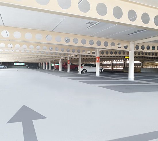
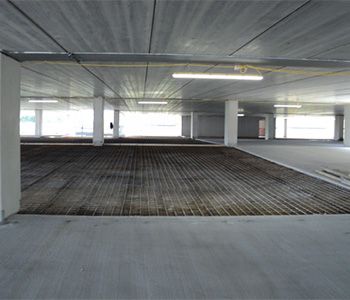
Dynamic crack bridging is a crucial property in protective coatings particularly in environments like multi-storey car parks (MSCPs). Here, movement, loads, structural weak points and temperature fluctuations can lead to cracking in the structural concrete. Where the concrete is protected with asphalt or coatings, cracking may also occur in these materials due to structural movement or breakdown over time.
Without protection, this cracking will allow water and chlorides to enter the structure leading to corrosion of the steel reinforcement and damage to the concrete. Dynamic cracks cyclically open and close typically due to thermal movement and vehicle loadings. Once cracks develop, damage can accelerate due to freeze - thaw cycles and spalling. Within limits, a dynamic crack-bridging waterproofing and surfacing system can accommodate the movement of cracks in concrete and existing coatings, ultimately preventing the ingress of damaging water or chlorides.
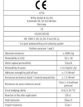
EN 1504-2 is the European standard which describes definitions, requirements, quality control and evaluation of conformity for surface protection systems for concrete, including crack-bridging coatings. It provides a standard by which coatings used in car parks and other concrete structures can be tested to meet vital performance criteria such as adhesion, durability and critically, crack bridging. EN 1504-2 certified* waterproofing and surfacing systems with appropriate performance can significantly extend the lifespan of concrete structures while maintaining a safe, functional, trafficable surface.
Here we will address why dynamic crack bridging is such an important property in coatings, where it is required in concrete car park structures and provide more details about the standard itself.
*A system which has been “tested” to EN 1504-2 is not the same an EN 1504-2 “certified” system.
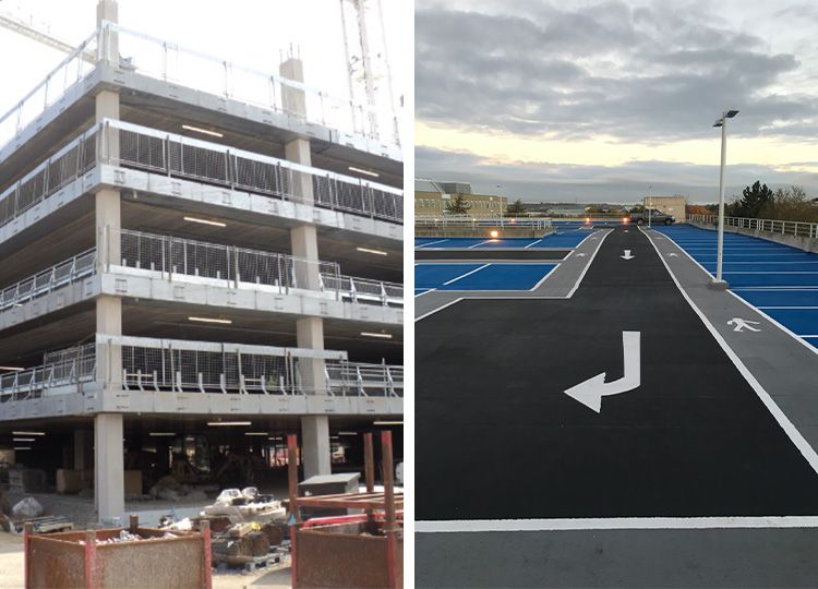
Multi-storey car park structures and risk of cracking
Higher risk of cracking
- Pre-cast elements (concrete planks)
- Double T units
- Steel frame
- Lightweight construction
- Lift slab
Lower risk of cracking
- Concrete frame
- In situ concrete decks
- Floating slabs (over insulation)
- Permanent metal formwork
Note: It is important to consult a qualified structural engineer to evaluate the condition of the structure.
Why is cracking in car parks so problematic?
The majority of multi-storey car parks are constructed primarily from steel reinforced concrete with the steel improving the tensile strength of the concrete. Without the steel reinforcement, the concrete is strong under compression but weak under tension, resulting in a high risk of cracking and failure under load. In reinforced concrete, the alkaline concrete itself provides protection to the steel reinforcement from corrosion via a passive layer. The primary risk to structural integrity is the corrosion of the embedded steel due to chlorides in road salts or as a result of carbonation.
Chloride ingress
Chlorides from road salts dissolved in water are driven in and deposited by vehicles, with the highest levels typically found on lower levels. If the concrete structure does not feature fully waterproof coverings, these dissolved chlorides can migrate through the concrete to the steel reinforcement. Where the concrete is cracked there may be a direct route through from the surface to the steel for chloride ingress. When chloride ions reach the steel surface, their combination with hydrogen ions contained in the water, creates acids which neutralise the alkalinity of the concrete.
The result is a breakdown of the passive film layer leading to localised corrosion of the steel reinforcement.
Carbonation
Carbonation is a process where carbon dioxide from the air diffuses into concrete and reacts with the calcium compounds in the cement paste in the presence of water. This reaction gradually lowers the concrete’s alkalinity, reducing the protective environment around embedded steel reinforcement. Once the pH falls to a critical level, the passive oxide film on the reinforcement can break down, making the steel susceptible to corrosion. The depth of carbonation increases over time and is influenced by factors such as concrete quality, cover depth, and exposure conditions.
In car parks this is a particular concern, as structural elements are frequently exposed to the weather and cycles of wetting and drying, which can accelerate the process.
Adequate concrete cover, appropriate mix design, and protective coatings are therefore essential to limit carbonation and achieve the service life expected of modern car park structures.
Common crack types in reinforced concrete:
- Flexural (bending) cracks
- Shear cracks
- Torsion cracks
- Punching shear cracks
- Cracks due to anchorage or lap failure
- Cracks induced by temperature changes
- Cracks due to freeze-thaw
- Cracks due to reinforcement corrosion
- Cracks due to alkali-silica reaction
Ref: The Concrete Society
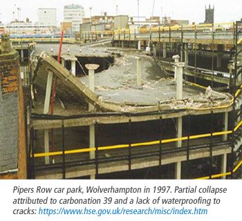
Corrosion
Any crack in a concrete structure will allow direct access of road salts (chlorides) and CO2 (carbonation), accelerating the corrosion processes.
The long term consequence will be structural failure.
Types of cracks in multi-storey car parks
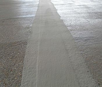
Plastic or dry shrinkage cracks
Plastic* shrinkage cracks occur in fresh concrete during the inital curing, due to rapid evaporation of water from the surface. They typically occur in the first 24 to 72 hours from concrete placement. Cracks will often be random, roughly parallel with varying lengths and depths and are often wider at the surface with diminishing width at depth.
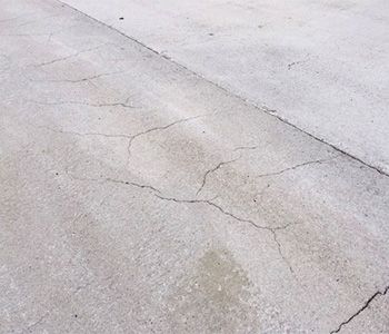
Drying shrinkage cracks occur when concrete loses excess water over time, causing a reduction in volume. They occur after the concrete has hardened, potentially weeks or months after placement. The cracks can be hairline or wide and are typically more uniform and evenly distributed than plastic shrinkage cracks. Slabs and thin sections are most vulnerable to drying shrinkage cracking due to their large surface area.
In multi-storey car parks, plastic shrinkage and drying shrinkage cracks are common. Drying shrinkage can often occur near corners, edges, and joints where moisture loss occurs from multiple surfaces. Since shrinkage cracking follows no specific pattern, it can emerge wherever restraint to movement exists, often forming at right angles to the direction of restriction.
Cracks which form during construction are easier to treat as they should be visible at the time of overlay. These cracks tend to move less than cracks which form post construction and the cracks typically only move in the horizontal plane from thermal movement. While these cracks may not directly compromise structural integrity, they still provide a path for water, chloride and carbonation ingress.
*Plastic refers to the concrete being in its uncured state
Dry shrinkage cracks:
- Form during construction
- Form due to non-recurring stresses
- Plastic shrinkage cracks occur during concrete curing
- Drying shrinkage cracks occur during concrete drying
- Often relate to restraint e.g. from corners or columns
- Limited movement compared to structurally related cracks, typically restricted to horizontal thermal movement
- Typically easier to treat due to lower movement and being visible at the time of overlay
Dynamic cracks
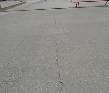
Reinforced concrete is designed with the assumption that it has minimal tensile strength, with steel reinforcement carrying the tensile stresses. As a result, reinforced concrete members subjected to significant loads often exhibit some cracking. However, concrete reinforcement controls the width of these cracks to ensure structural durability, serviceability, and aesthetics. Maximum allowable design crack widths (typically 0.3mm) under normal service loads are set to maintain durability, watertightness, and visual acceptability.
Crack width limits vary based on structural function and exposure. While some cracks may exceed specified limits, their impact depends on location, structure type, and environmental conditions, requiring engineering judgment to assess their significance.
“For reinforced concrete structures, crack widths are limited to 0.3mm. For prestressed concrete structures and for bridges,the maximum crack width is related to the environment.
In all structures, a few cracks will be wider than specified, but this should not necessarily cause concern unless the wider cracks are at critical locations. Some engineering judgement is required to determine their significance and this will depend on the location in the structure, the type of structure and the environment.”
Dynamic cracks:
- Form post construction
- Dynamic in nature: subject to ongoing movement
- Movement can be in multiple planes
- Affected by dead loads and dynamic loads
- Subject to thermal expansion and contraction cycles
- Can be subject to rotational movement
Ref: Concrete society
Cracks which form post construction will be dynamic as they are subject to the movement which caused the crack, thermal movement and dynamic movement through varying loads on the structure. This movement may be in multiple planes, particularly where rotational movement occurs e.g. at the ends of pre-cast concrete planks over beams.
What is EN 1504-2?
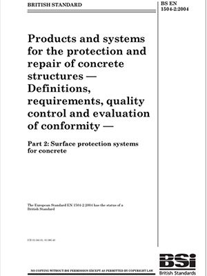
EN 1504-2:2004 is a European and British standard (BS EN 1504-2) titled “Products and systems for the protection and repair of concrete structures. Definitions, requirements, quality control and evaluation of conformity. Surface protection systems for concrete.”
This standard specifies requirements for the identification, performance (including durability aspects), safety, and evaluation of conformity of products and systems used for the surface protection of concrete structures. EN1504-2 includes requirements for products and systems for concrete protection that cover a wide range of applications. It is applicable to anti-carbonation paints, hydrophobic treatments to prevent moisture and chloride ion ingress, as well as crack bridging systems that could be used on car park deck surfaces.
Its primary aim is to enhance the durability of both new and existing concrete and reinforced concrete structures through appropriate surface protection measures. Triflex are closely involved with independent industry leading assessment bodies throughout the UK and Europe. Our waterproofing, surfacing and marking systems have been recognised by these external bodies for their exceptional quality and performance.
EN 1062-7: Determination of crack bridging properties
The test method used for determining crack bridging properties in EN 1504-2 is defined under EN 1062-7, titled “Paints and varnishes - Coating materials and coating systems for exterior masonry and concrete - Part 7: Determination of crack bridging properties”. The standard specifies a method for testing crack bridging properties of coatings used in both protection and repair. The procedures determine how well a coating can bridge cracks under static or dynamic movement at different temperatures. It helps classify coatings by their crack-bridging class, guiding their suitability for structures subject to cracking or movement.
Overview
- The coating is applied to a concrete sample
- A defined crack is made in the concrete substrate at a nominal crack point
- The sample is conditioned to a specific temperature
- The crack is continuously widened at a defined speed at the specific temperature
- A measurement is taken when either the coating or coating system fails, or the
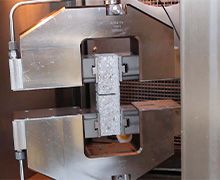
The crack width is continuously enlarged at a defined speed. The measurement is taken when either failure occurs in the coating or coating system or when the required crack width is reached.
The crack width varies periodically within defined limits. The measurement is taken when either failure occurs in the coating or the coating system, or when the dynamic cycle is completed. For the most severe test under the standard (B4.2), the total number of crack cycles is 21,000, it takes 9.25 hours and it is all carried out at a defined temperature.
Simulation of building movement:
• 1,000 larger movements (0.2mm to 0.5mm)
Simulation of dynamic / traffic loads:
• 20,000 smaller movements (10,000: 0.45mm and 0.55mm, 10,000: 0.15mm and 0.25mm)
Why does dynamic crack bridging matter?
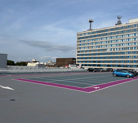
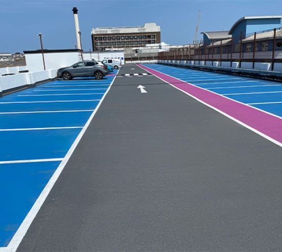
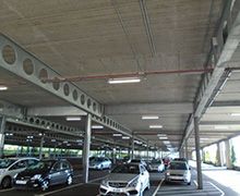
Car park top decks and ramps receive the most severe exposure conditions, including thermal movements that induce crack opening, and solar radiation that accelerates embrittlement of coatings. Protection with waterproofing and surfacing solutions that have dynamic crack bridging properties which reflect the intended use environment are necessary.
For the UK and European climate, systems that can demonstrate flexibility and integrity at -20°C, are considered appropriate to these exposure conditions. The dynamic crack bridging ability of the coating contributes to increased durability and life cycle length for the waterproofing, and in turn the structure; important elements for sustainable solutions for the built environment.
Today in ageing car parks, the waterproofing, surfacing and protection systems may also protect the investments made in concrete repairs. If owners have invested in sacrificial anodes, then protecting it with the appropriate waterproofing and surfacing is a must.
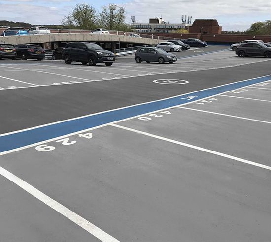
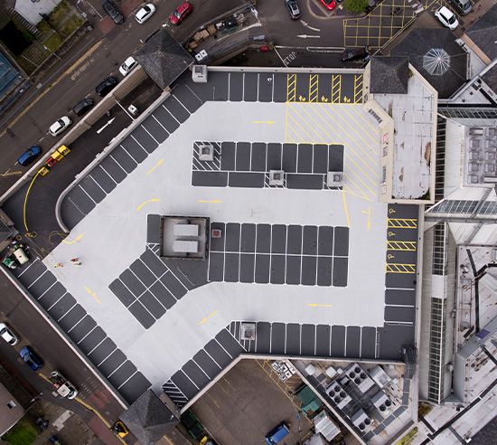
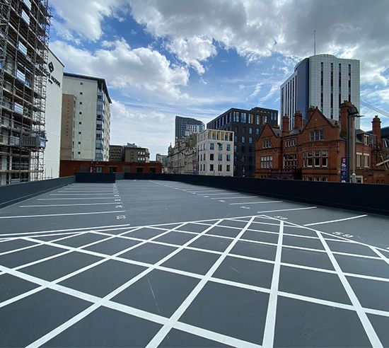
Where is dynamic crack bridging needed?
A waterproofing, surfacing and protection system with crack-bridging properties prevents water and chloride ingress through cracks, inhibiting steel corrosion. Such systems can actively contribute to extending the lifespan of the structure and reduce maintenance costs. This ensures a safe, durable, and cost-effective environment for vehicles and owners.
Systems with dynamic crack bridging properties are needed in car park areas where the structure is subjected to repeated movement or stress, to maintain integrity of the protection.
Key locations include:
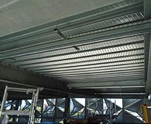
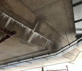
1. Beams: Where pre-cast elements and in situ concrete decks are supported at beams, deflections in the adjacent less supported area can result in rotational movement causing cracking over the beams.
2. Day joints and crack inducement: Day joints and induced cracks (e.g. saw cuts) are weak points in the construction and therefore subject to an increased risk of movement.
3. Driving and parking surfaces: The decks of car parks are subjected to heavy traffic loads, vibrations, and dynamic stresses from vehicles, making them prone to cracking. The whole surface should be considered if crack locations cannot be predicted.
4. Ramps and sloped areas: These areas experience additional stress from vehicles braking, accelerating, and turning, increasing the risk of crack formation.
5. Perimeter walls and edge details: These regions can experience cracking from restraint.
6. Repairs and transition zones: Areas where two different materials or structural elements meet often experience differential movement, leading to cracking. Addressing dynamic crack bridging in these critical areas ensures structural durability, prevents chloride and water ingress, protecting the car park from premature deterioration caused by corrosion, freeze-thaw cycles, and chemical exposure
Practical provision of dynamic crack bridging
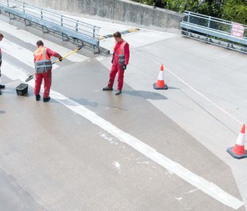
The waterproofing surfacing and protection system must meet the structural protection needs. When addressing dynamic crack bridging in car parks, the decision between treating local areas versus whole areas depends on the extent, severity, and location of the cracks, as well as the condition of the structure.
Dynamic crack bridging capabilities can be achieved through localised reinforcement, or full reinforcement.
Localised reinforcement
- Isolated cracks or specific problem areas are identified from a visual survey
- Cracking location can be predicted and extrapolated e.g. if most beams have cracking, treat over all beams
- Focuses on areas only where needed
- Complemented by a flexible waterproofing membrane to the main area
Full reinforcement (whole deck dynamic crack bridging)
- Widespread cracking or significant deterioration is present across the structure or the structure is high risk (over occupied premises, steel frame with pre-cast concrete units)
- Preventative maintenance is desired to avoid future damage and ensure uniform protection
- Structural movement or environmental exposure affects large portions of the deck or car park
- Provides comprehensive protection, addressing both existing visible cracks and potential future ones
- Enhances durability and waterproofing for the entire area, reducing long-term maintenance needs
Reinforcement in Triflex waterproofing systems utilise a polyester fleece reinforcement, coupled with Triflex’s technologically advanced PMMA resin. This is often termed “reinforcement” or “overbanding” in waterproofing systems.
Triflex systems are certified to EN 1504-2
Recognised throughout Europe as the industry leaders, Triflex offers a dedicated range of solutions for multi-storey, underground and surface car parks.
The most relevant standard used for exposed car park decks is considered to be B4.2 at -20°C. Other test basis e.g. B3.1 / B4.1 etc. and tests at higher temperatures e.g. -10°C are much easier to pass.
Triflex ProPark fully reinforced system achieves class B4.2 at -20°C.
Downloads
Click here to download
your free copy:
Triflex guide to dynamic crack bridging:
Multi-storey car parks
Click here to download
your free copy:
Triflex solutions for failing asphalt:
Multi-storey car park decks and ramps